


Enquire about "MX250 Microprocessor Controller" Now
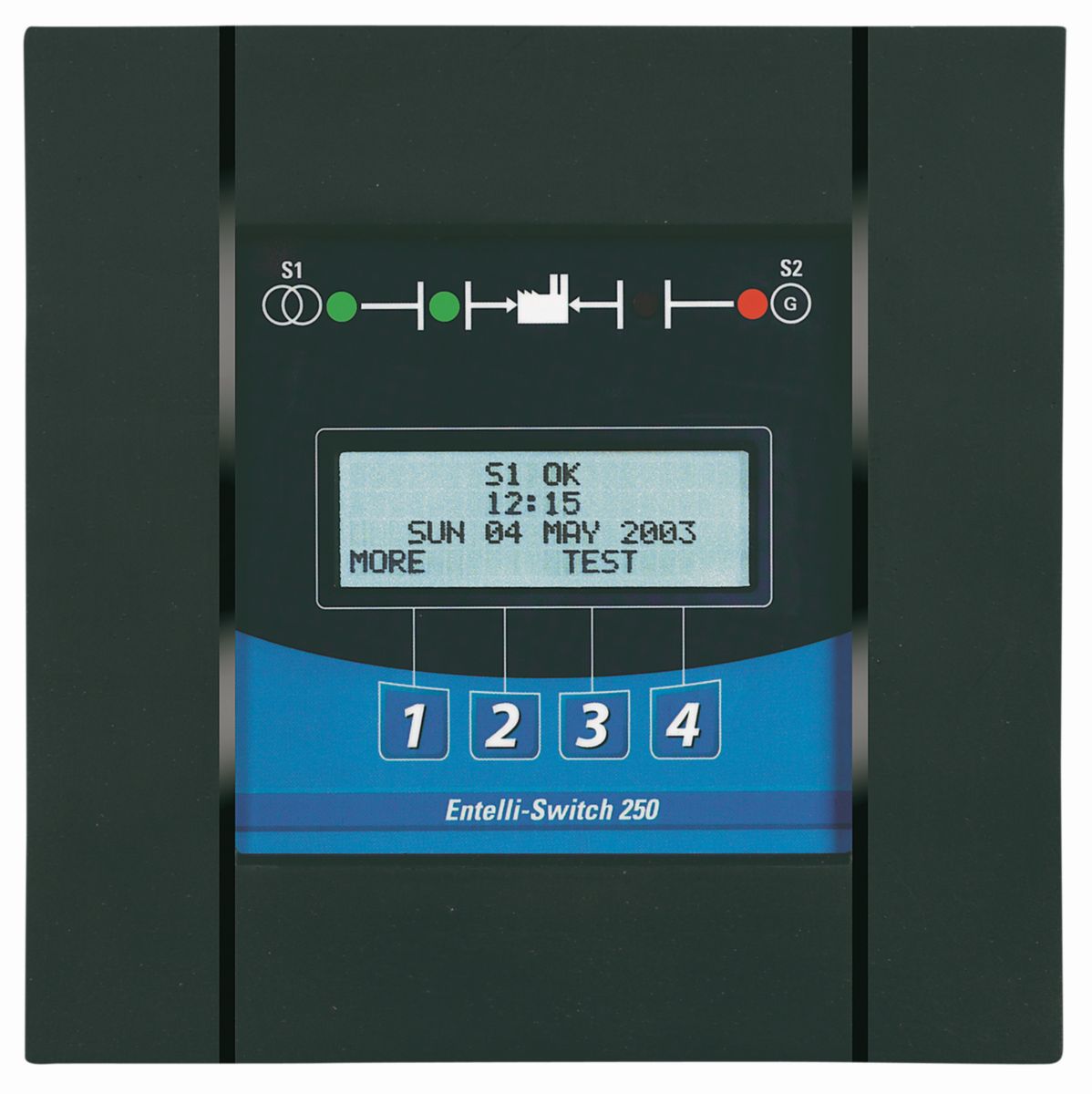
MX250 Microprocessor Controller
Features and Benefits
- Available to support ALL transfer modes:
–Open, Delayed and Closed Transition - User-friendly programmable engine exerciser,with or without load, at ANY interval in a one-year period
- A wide variety of operating voltages available in a single controller for most domestic and international applications
- Real-time display of ATS status, including active timer(s)
- Multiple levels of user-defined password protection
- Serial communications allowing connectivity with other ATS’s, Caterpillar® Switchgear, and SCADA systems
- Time-tested synchronous logic automatically measures phase angle and frequency allowing disturbance-free transfer
- Unsurpassed statistical ATS/System monitoring available in real-time
- Elevator pre-signal contacts automatically bypassed if the selected source fails, minimizing time an elevator is without power
- Universal Motor Disconnect (UMD) sends a pre-signal, post-signal or both to any motor control center. Not bypassed in an outage,the UMD ensures safety in the event of a single phase loss
- Voltage unbalance detection standard
- Also includes all standard MX150 features
- Back-lit/temperature compensated LCD display (includes the display of source voltage and frequency, exercise time, delay options and source condition)
- Close differential 3-phase under-voltage sensing of source 1, factory standard setting 90% pickup, 80% dropout; under-frequency sensing of source 1 factory setting 95% pickup;voltage and frequency sensing of source 2,factory standard setting 90% pickup voltage,95% pickup frequency.
All factory settings are operator adjustable. - LED indicators for ATS position and source availability
- Plant exerciser clock (configured for 1, 7, 14 or 28 day run selections)
- Built-in time delays with count-down display
- Push button to bypass time delay transfer/retransfer
- Transfer/commit/no commit selection In-phase monitor
- Event logging (last 16 events)
- A test is standard (fast test/load/no load) to simulate source 1 failure
- automatically bypassed should source 2 fail.
| Technical Summary | |
|---|---|
| Rating Range | Switch Dependent |
| Transfer Type | Application Dependent |
| Switch Type | Application Dependent |
| Controller Specifications | |
|---|---|
| Undervoltage Dropout for Source 1 and Source 2 | 75-98% of nominal |
| Undervoltage Restore for Source 1 and Source 2 | 85-100% of nominal |
| Underfrequency Dropout for Source 1 and Source 2 | 90-100% of nominal |
| Delay for Engine Cool Down (U) | 0-60 minutes |
| Delay Transfer to Nonpreferred Source (W) | 0-5 minutes |
| Delay NeutralTransition Time Delays (DT,DW) | 0-10 minutes |
| Storage Temperature | (-30u02daC - 75u02daC ), -22u02daF - 167u02daF |
| Operating Temperature Ambient |
40 - 400 amp molded shell (-20u02daC to 65u02daC) , -4u02daF to 149u02daF 40 - 4000 amp all others (-20u02daC to 60u02daC), -4u02daF to 149u02daF |
Standard Equipment
- Performance
- ESD immunity test per EN61000-4-2 Class B(Level 4)
- Electrical fast transient/burst immunity test perEN61000-4-4
- Conducted and Radiated Emissions per EN55022Class B (CISPR11) (Exceeds EN55011 & MILSTD461 Class 3)
- Voltage dips and interruption immunity EN61000-4-11
- Conducted immunity test per EN61000-4-6(ENV50141)
- Ringing wave immunity per IEEE 472(ANSIC37.90A)
- Surge immunity test per EN61000-4-5 IEEE C62.41
- UL, CSA and IEC listed
- Radiated RF, electromagnetic field immunitytest per EN61000-4-3 (ENV50140) 10v/m
- User Friendly Operation
- Weather and tamper resistant touchpad
- Through-the-door programming and display
- Multipurpose display: LEDs for continuous monitoring of switch position and source availability; a four line by twenty character LCD display for settings, functions, programming and annunciation
- Simplified keypad entry – menu-driven system is designed for ease of use
- Built-in diagnosis with displays for ease of troubleshooting
- Additional Features
- User settings are unaffected by power outages
- Built-in programmable exerciser uses separate microcontroller with independent battery back-up to serve as clock/calendar – battery failure will not affect switch operation
- Built-in electrical operator protection
- Inputs are optoisolated for high electrical immunity to transients and noise
- Source connection and transfer data logging
- Separate line voltage components for controller isolation
- Watchdog circuit for microprocessor operation